English Deutsch
How to get information about entities
The main concept of the CAD Drawing Database XML structure is that all the information contained in the drawing file is structured in a tree form.
Each object of the file is represented as an element node with a set of attributes. The attribute defines a specific object property, attribute name and attribute value consisting of strings of characters.
To get the CAD Drawing Database XML structure, it is necessary to execute the GET XML API instruction.
The XML structure can be represented in the following way:
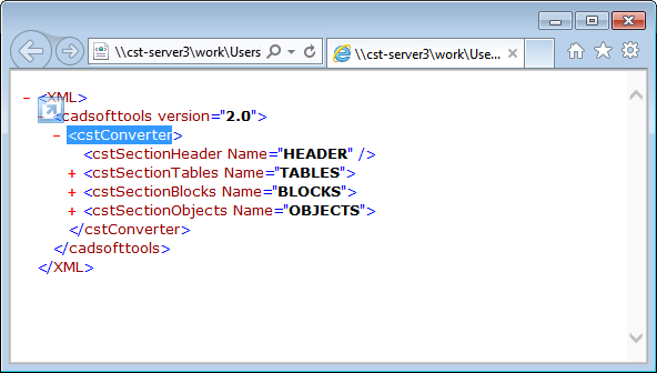
cstConverter is the drawing in this structure. There are the following sections below it:
HEADER
TABLES
BLOCKS
OBJECTS
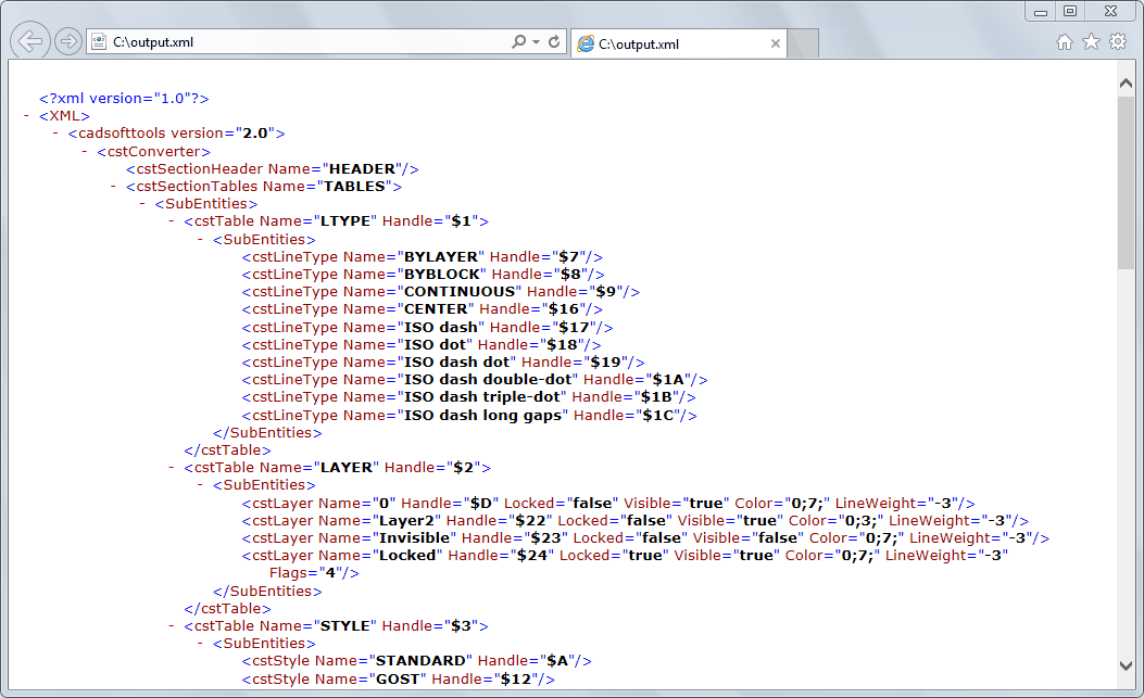
The TABLES section saves line types, layers, styles and other information. Entities are in the BLOCKS section in the <cstBlock Name="*MODEL_SPACE"> block.
The <get> command returns either the whole drawing XML structure or the selected object of the drawing data and all its child objects. It is convenient to use the result of the <get> command as parameters of the <add> XML API command where it is necessary to specify the XML structure from the SECTION to which the object belongs, to the table or block, where the object will be added via the <add> XML API command.
It is necessary to know that there is no ENTITY section in the XML structure. This section is replaced by the *MODEL_SPACE block that is always present in the drawing database. Entities, unless it is otherwise stated by the XML structure, are always added to the BLOCKS section into the block named *MODEL_SPACE. That is why if you add entities using the <add> command, you should not specify the BLOCKS section and the *MODEL_SPACE block. All entities are added there by default.
Objects in the drawing database are created by the class name. You can find the list of all supported objects, which can be created by the class name, in this help file in the Entities part.
XML API commands allow changing object properties in the drawing. For this purpose it is necessary to change the object attribute via the XML command. All attributes, except for the read-only attributes, can be changed with the help of XML API commands.
You can find the full list of attributes related to a certain object class in the description of a particular object.
For example, the cstLine class object representing a Line in the drawing database has the following attributes:
Syntax:
<cstLine LineWeight ="Double" Handle ="EntHandle" Flags ="Integer" LineType ="EntName" Layer ="EntName" Color ="ColorCAD" LineTypeScale ="Double" Point ="FPoint" Thickness ="Double" Extrusion ="FPoint" Point1 ="FPoint" Length ="Double" Angle ="Double" />
Parameter |
Type |
Description |
Line Weight in mm. |
||
Flags are not suggested for usage. They have different meanings for particular entities, most of them are represented also directly via other attributes. |
||
Name of a LineType. |
||
Name of a Layer. |
||
Color specified with TsgColorCAD. |
||
Scale for Line Type elements. |
||
3D Point defining entity. |
||
Thickness. |
||
Extrusion direction point. |
||
3D point defining entity. |
||
Length value. |
||
Angle value. |
Example:
<?xml version="1.0" encoding="utf-8"?> |
Go to CADEditorX